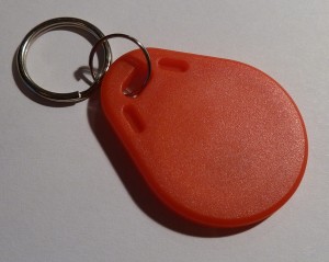
I am in the process of installing a Nexus 7 Tablet permanently in my Car – Using it for Navigation software and playing music.
I need to be able to tell the Nexus 7 to pause playback of music, and go to sleep. The easiest and most simple way is to touch a NFC tag to it, that tells it to do just this (Using a combination of NFC Task Launcher & Tasker)
But, how to enable the tag at will ?!
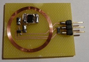
Solution: Put a CMOS switch in series with the antenna of the tag – this way it will only be readable when i tell it to!
A good solution is the 74HC4066 or even the DY411DY, but those are just too big an complicated. Why not resort to a single CMOS switch – Enter the 74LVC1G66.
A small SOT353 device that does it all, albeit a bit small for most soldering irons, but nothing my Weller WD1000M can’t handle.
I drew up a board in Eagle cad and milled a PCB. It didn’t work in the first try, it seems I damaged the RFID chip when removing it from the blob of glue inside the tag, so next chip i mounted sits on a big glob of glue, no need to risk damaging another chip!
I the second try, it works perfectly! – The chip needs a supply voltage of 3,3 or 5V and a logic high signal to trigger the Tag “ON”
Here is a Video of it in action!:
Attached is the Eagle files for your perusal.
EAGLE FILES: RFID_brd


December 17th, 2012 at 13:01
[…] but [Per] wanted to pause his tunes and tell the tablet to go to sleep with an NFC tag. This means building a an NFC tag he can turn on and off, an interesting problem to say the […]
December 17th, 2012 at 13:20
[…] but [Per] wanted to pause his tunes and tell the tablet to go to sleep with an NFC tag. This means building a an NFC tag he can turn on and off, an interesting problem to say the […]
December 17th, 2012 at 18:24
This is a very interesting approach. I found it through hackaday. I wonder if this would have been possible without opening the tag at all. Right now I am researching Antennas for my DCF77 project http://blog.blinkenlight.net/2012/12/01/dcf77-project/ . Due to this research I think it should be possible to achieve a similar effect without opening the tag at all. The first idea would be to place a single loop between the tag and the NFC transceiver. Ideally the loop should be centered around the tag and parallel the tag’s antenna. Alternatively it could surround the transceiver in the same manner instead.
Now you open or close the loop exactly as you controlled the RFID antenna. Closing the loop should suck enough power out of the field to make communication impossible. If necessary the tag needs a little bit more distance from the phone.
The second idea would be to have a double loop like so:
/————————–\
//—–\ /—-\ |
|| | | | |
|\———–S———–/ |
\—–/ \—–/
with a switch at position S. One loop around the transceiver the other around the tag. Closing the loop should make the tag visible to the transceiver.
Of course I am just speculating. If you find the time I would be pleased to learn if one of these approaches actually work. If it works you would have an even simpler approach and maybe another hackaday coverage 😉
December 17th, 2012 at 18:42
[…] but [Per] wanted to pause his tunes and tell the tablet to go to sleep with an NFC tag. This means building a an NFC tag he can turn on and off, an interesting problem to say the least. The easiest way to do this is with a CMOS switch, but a […]
December 17th, 2012 at 19:02
Yeah, i actually toyed with the idea of just placing a loop between the two to “short-circuit” the field and stop communication. I will have a try at it sometime soon, and update the post with my findings.
Actually i have seen a neat trick done on 125 KHz tags in car immobiliser tags. I looked at an alarm with remote-start of the motor, to make remote start possible, you mounted an extra chip in a box, and from that a cable ran to a loop antenna you placed around the ignition key opening, completely passive, but enough to work!
December 17th, 2012 at 19:43
Hey this is a very interesting solution! I am also interested in how you come along with putting your Nexus in the car as a replacement. I have been considering the same thing (I have a RaspberryPi on the way to make a brain for my car but a Nexus would work even better).
How are you handling sound to your speakers? Just running it through a 4/5 channel? What about power? Also, I’m curious: do you plan on handling peripherals such as reverse cameras etc? These are all things I’ve been thinking about how to handle. I have not had time to dive in yet, but hope to soon. I think I could get a usb hub to expand but I’m not sure. I also need to be able to take input from my Arduino setup which reads from the OBD-II port and interprets CAN Bus signals and reads from some sensors I have setup.
I’m rambling. Look forward to future posts!
December 17th, 2012 at 20:01
I have been using an integrated 7″ Touchscreen from LinITX + a Macmini running XP and Garmin Mobile PC for nav and Centrafuse for Music for the last 4 years, but there was too many problems, and GMPC is a piece of shit…
I have two amps, one under each seat, in all 6 channels, i still have a HU, but the front of the radio is relocated to the ceiling via a long cable and some signal amplification, the HU is mounted under the drivers seat along with the sub amp.
My old LinITX monitor had inputs for Reverse camera, but as it is now, i do not have ability to view that. I’m going to install a second LCD monitor in the sunvisor for that use.
Maybe i should take it apart someday and document it here on the blog if there’s interest.