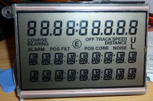
I have these displays from an old Ship navigator i scrapped for parts.
It was a Philips Navigator, model F 505-2
I kept the displays as the three PCF8576 controller chips sat nicely behind the display glass, so i cut the PCB along the smart mechanism that holds the display glass and elastomers tight to the PCB 🙂
It’s a quite curious design, the first 9 digits are standard 7-segment letters, and a bunch of symbols.
The last 18 digits are 11-segments, nor 12, 14 or 16 which seems to be the “standard” around…
Each of the last 18 characters needs 12 data bits, so writing them becomes quite a challenge, as one can only send 8 bits at a time with the I2C-bus. So writing the first character is 8 bits and you can control 8 segments, and the next byte, the first nibble is the remaining segments for the first digit etc.
So addressing the display is like this
- DIGIT1(8 Bits)
- DIGIT1(4 Bits)/DIGIT2 (4 Bits)
- DIGIT2(8 Bits)
- Etc….
Before scrapping the navigator completely, i hooked up my logic analyser to see how the chips were adressed via the I2C-bus.
A shot with all segments lit:
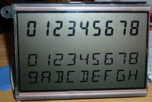
I wrote a simple and _ugly_ program for the Arduino to test the display, and the results can be seen here:
You can get the Arduino-program here.


April 8th, 2013 at 19:55
Nice example! I am trying to do the same with another display controlled by a PCF8576 (also from an old philips device) Could you give me some details about the wiring?
TIA and thanks for sharing your experience
Carlos
April 8th, 2013 at 20:10
Wiring? Just wire the I2C bus like stated in the datasheet.
April 6th, 2014 at 04:50
I wouldn’t know how to run a logic analyser if I had one.
But now I know how to control a few really nice LCD I happened upon.
Thank you for sharing!
January 8th, 2015 at 12:36
Hi. Thanks for sharing, your Post is Pretty impressing. I am currently working on an analog “Problem”.
I have a Machine, with an LCD driven by 4 PCF8576C IC’s. This Display is defective and I would like to emulate the PCF8576C Devices with some little MSP430 from TI, to interpret this Data and send it afterwards to an Arduino to Display it over an XBee Shield on a little Handheld.
But currently I have some trouble to interpret the Communication. I’ve sniffed a bit with the Logic Analyser to see whats going on, but it’s kinda difficult for me to interpret this Informations. (First Time I’m using a Logic Analyser)
Maybe you have some Advices for me?
January 8th, 2015 at 18:21
Hmm, no real advice regarding emulating the chips. It’s not very easy. Which kind of equipment do you have the employs this display ?. Maybe you could tap the data you need at another point.
January 11th, 2015 at 17:18
Hi. Thanks for your answer. My Problem is, that the Device that sends the Informations to the Display is this one: http://www.sekospa.com/system/pictures/164/normal/SAM_5_450-90-A_1000x750_72.jpg?1362403674
The Display only has 8 14-Segment Digits (therefor it is using 4 IC’s as seen on the Datasheet). It shouldn’t be a Problem to emulate the Chip. The 4 TI MSP430 can read the Data from the I2C Bus.
The only Problem is, that I have no Idea how I could know for example how the Controller would send a “1” or the letter “a” to one Segment. You are also using the 14-Segment Digits here, how did you know which Information you’ve to send to get this Result?
Thanks 🙂
January 11th, 2015 at 18:38
Well, the way i found out how to control the display, i connected it up to the original circuit, let it initialize and write data while i had a logic analyser connected at the same time. I wrote some code that emulated the device, and everything worked. Then i tried changing the bytes, and by that i could figure out what went to what.