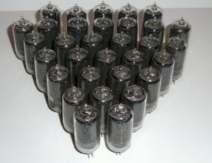
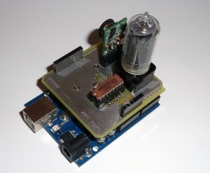
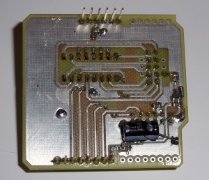
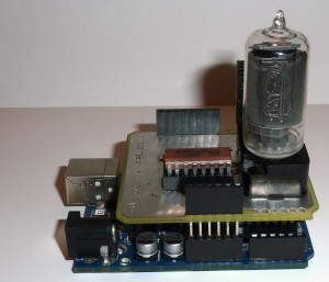
 Recently, i purchased a big lot of Philips ZM1000 Nixies, and needed a test PCB to test out if all was good – i got sockets for a number of the tubes, so i settled on making a PCB with the correct socket, so I easily can test them.
Being fond of the Arduino, i just thought, why not make it an Arduino shield – this way it’s a nice compact solution, powered by the USB-port, and no extra cables needed.
I earlier on aquired one of the real nice high voltage supplies, perfect for nixies from Taylor Electronics
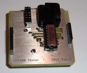
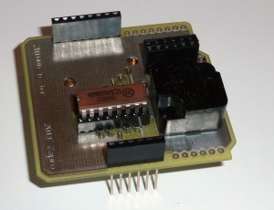
So i made a single PCB that fits the small power supply module, a socket for a 74141 Nixie driver, and a socket for the ZM1000 tube.
I milled the PCB on our PCB milling machine in the local hackerspace where i frequent, Labitat
I did not mount all the headers on the finished PCB, since they are not in used. The use of stacking headers are a little waste, since there is no way I can mount anything on top of the Nixie PCB, but they make the PCB headers more mechanically stable, since they are soldered on on the bottom side of the PCB.
A small video of the circuit in operation, running a simple counting program, testing all digits: Youtube
Video:
You can get the Eagle PCB files for the project here: ZM1000_Shield
