Hi folks. A fellow member in Labitat, Peter assembles electronics for Makerbot, at the moment he is making:
- Makerbot Motherboard v2.4
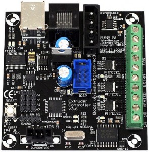
- Extruder Controller v3.6
- Stepper motor driver v3.3
- Mech endstop v1.2
I bought a set of electronics for my RepRap Mendel that is in the making at the moment.
Peter was foresighted and fitted an Atmega328p instead of the bog standard Atmega168 that is a bit old today, this way the EC will have room for improvements which is not bad!
The standard ReplicatorG software cannot program the Atmega328p at this moment, but you can modify it by compiling the code your self, and add something in the firmware.xml – but i don’t see this as a good solution, since you won’t get updated firmware from Makerbot this way.
If you want to program your Extruder Controller fitted with a Atmea328p, follow this guide and it will work out for you:
http://wiki.makerbot.com/v2-firmware
A beginner’s mistake was writing
scons -f SConstruct.extruder
scons -f SConstruct.extruder port=/dev/SERIALDEVICE upload
It didn't work because i had not read all the instructions. It defaults to compiling
the code for the old Extruder Board 2.2 and not the Extruder Board v3.4
So running this made it work:
scons -f SConstruct.extruder platform=ecv34scons -f SConstruct.extruder flatform=ecv34 port=/dev/SERIALDEVICE upload
This compiles the code from source to your Atmega168-fitted boards. To compile for
the Atmega328p you need to do these changes:
inside the /G3Firmware/v2/src/Extruder/ there is a SConscript file, edit this.
if platform == 'ec36':platform = 'ecv34'default_baud = '19200'mcu='atmega168'
Edit it so it says this:
if platform == 'ec36':platform = 'ecv34'default_baud = '57600'mcu='atmega328p'
Further down the file change this:
elif (platform == 'ecv34'):default_baud = '19200'mcu='atmega168'
So it reads like this:
elif (platform == 'ecv34'):default_baud = '57600'mcu='atmega328p'
With these changes you can compile for the Atmega328 ;-)


