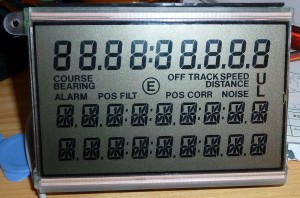
I have these displays from an old Ship navigator i scrapped for parts.
It was a Philips Navigator, model F 505-2
I kept the displays as the three PCF8576 controller chips sat nicely behind the display glass, so i cut the PCB along the smart mechanism that holds the display glass and elastomers tight to the PCB 🙂
It’s a quite curious design, the first 9 digits are standard 7-segment letters, and a bunch of symbols.
The last 18 digits are 11-segments, nor 12, 14 or 16 which seems to be the “standard” around…
Each of the last 18 characters needs 12 data bits, so writing them becomes quite a challenge, as one can only send 8 bits at a time with the I2C-bus. So writing the first character is 8 bits and you can control 8 segments, and the next byte, the first nibble is the remaining segments for the first digit etc.
So addressing the display is like this
- DIGIT1(8 Bits)
- DIGIT1(4 Bits)/DIGIT2 (4 Bits)
- DIGIT2(8 Bits)
- Etc….
Before scrapping the navigator completely, i hooked up my logic analyser to see how the chips were adressed via the I2C-bus.
A shot with all segments lit:
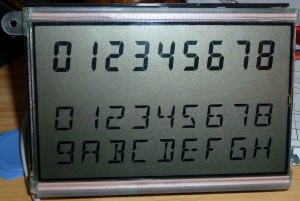
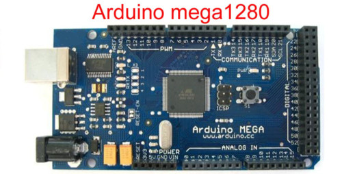
I wrote a simple and _ugly_ program for the Arduino to test the display, and the results can be seen here:
You can get the Arduino-program here.


